INPUTS
Inputs are the signals from sensors all around the engine that the ECU relies on to keep the engine efficiently and smoothly.
TPS testing
The first sensor tested was the TPS (throttle position sensor) this test is done with engine off but ignition on the sensor was tested by placing the multimeter probes onto the board that allowed us to get readings from the different sensors on the motor, but in real life this cannot be done so you can use the back probing method to get readings from sensors(more information on back probing can be got from the inputs and outputs using oscilloscope post), this was the method to how each of the sensors was tested .First the throttle was tested when it was closed or at the idle position, it gave a reading of 0.5 volts then the throttle was opened up fully and the sensor gave a reading of 3.9 volts it was tested by setting the multimeter to DCV (direct current voltage). The TPS sends the voltage to the ECU (electronic control unit) as a signal this tells the ECU how open the throttle is and therefore it can estimate much air could be going into the motor and adjust the fuel injected into the combustion chamber correspondently to keep the air/fuel ratio at stoichiometric mixture which is 14.7:1 or 14.7 parts of air to one part of fuel. Stoichiometric must be kept as this is usually the most efficient ratio for the motor to run on. The greater voltage or signal that the ECU receives the more fuel the ECU keeps the fuel injectors open to keep the correct air/fuel ratio. If the TPS is faulty i.e. there is flat spot where bad contact is being made, this could also be a voltage decrease as the throttle is opened more instead of the normal increase in voltage that is sent to the ECU. This means the TPS tells the ECU that the throttle is open less than what it actually is this could cause a power lag as the air/fuel mixture would be to lean because not enough fuel is being injected into the combustion chamber and the engine would be down on power for a brief moment. The throttle position sensor is located on the opposite side of the air intake to the throttle control.

COOLANT TEMP SENSOR
The next was done when the engine was running but this is done immediately when it is cold so that it can compared with when the engine was warm. This test was on the coolant temperature sensor, when the engine or coolant is cold the sensor sends 2.5 volts to the ECU and when the engine has warmed up this sensor was tested by setting the Multimeter to DCV, the sensor sends 0.5 volts to the ECU the greater voltage is sent to the ECU when the engine is cold so that the ECU knows what temperature the engine is and therefore whether the engine needs a rich air/fuel mixture when it is cold. The engine needs a rich air/fuel mixture when it is cold as fuel condenses on the cold surfaces of the combustion chamber and the fuel loses its explosive abilities when it condenses back to a luquid, a rich air/fuel mixture would be 12:1 or less. So more fuel is injected into the combustion chamber so that there is still enough fuel to keep the engine running when it is cold. Once the engine has warmed up the coolant temperature sends less voltage to the ECU this is so that the ECU knows that the engine has warmed up and not as much fuel needs to be injected now because the fuel cannot condense on the hot combustion chamber walls and now less fuel is required to keep the engine running as none of it is condensing and all of it can combust. If there is something wrong with the coolant temp. sensor then the ECU does not know whether the engine is cold or warm and cannot give the correct air/fuel ratio this could cause the engine to run rough as it the engine could run to lean and fuel won't be as combustible. A lean air/fuel mixture would be 17:1 or more. If the coolant temperature sensor is not working properly i.e it is sending to high of a voltage to the ECU when it has warmed up, then the ECU thinks that the temperature in the engine is less than what it actually is and the ECU will open the fuel injectors for a longer period of time and a rich air/fuel mixture is created. This would cause an increase in power but a decrease in fuel economy as more fuel is being injected than what is needed. If the coolant temperature sensor sends to low of a voltage to the ECU then the ECU thinks the engine is warmer than it actually is this could cause the engine to run roughly when it is cold and a lot of the fuel is condensing on the cold surfaces of the combustion chamber but this should become better as the engine warms up.

RPM sensor
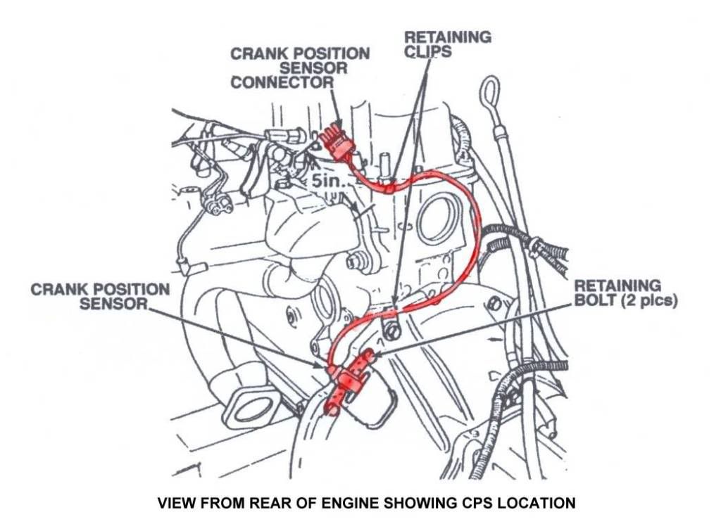
The next test was to check the crank shaft and cam shaft sensors otherwise known as an RPM sensor as these sensors are usually located in the distributor of cars that have ECU's but do not have coil over plug arrangements, these sensors are usually tested by setting the multimeter to ACV (alternating current voltage) or it can be measured by setting the multimeter to Hertz (Hz) or cycles per second then checking both the crank shaft sensor and the cam shaft sensor whilst the engine is running. Then check the Hz (hertz) for the two sensors by setting the multimeter to Hz. The crankshaft and camshaft sensors purpose to let the engine ECU know at what point the engine is so that it knows when to fire the spark plugs and the fuel injectors. The ECU measures the frequency or Hz of that the sensor is putting out to know what the engine speed is or by how much the engine is revving so that fuel injectors can be opened at the correct time and the spark can occur at the correct time. At idle the crankshaft sensor should read about 0.8v(ac) and the camshaft 0.25v (ac), and the Hz should be about 37Hz for the crankshaft sensor at idle and 80Hz at 2500RPM and at idle the camshaft sensor should be 20Hz it shouldn't increase to much more when the engine is at revs. If either the crankshaft sensor or the camshaft sensor fail then the engine will not run because these sensors tell the engine where the crankshaft is located or piston position, and the camshaft sensor tells the ECU what stroke the cylinder is on whether it be intake, compression, power or exhaust. This sensor lets the ECU know when to inject fuel and when to fire the spark plugs if the arrangement is coil over plug. Usually when a RPM sensor becomes faulty it does not send any voltage to the ECU so the ECU does not know that the engine is trying to started and the engine therefore will not start nor will it run as the ECU does no know when to fire fuel injectors or the spark plugs.

MAP sensor

AIR TEMP SENSOR
The last sensor to be checked was the air temperature sensor this was tested by having the multimeter set to DCV, first it must be checked when the engine is cold which should be around 2.5 volts or more if the outside air is relatively warm and decrease to 2.3 volts or less when the engine has warmed up. The purpose of the air temp. sensor is to let the ECU know the temperature of the air going into the engine, this is because during cold conditions air is much more dense and therefore more fuel is required to keep the correct air/fuel ratio, however in hot conditions air is less dense and becuase there is less air, less fuel is required to be injected to keep the correct air/fuel ratio. If the air temp. sensor does not work then the ECU does not know how dense the air is and will not know how much fuel to inject into the combustion chamber. However this is not such a big problem as the difference between hot and cold conditions and the fuel required is so small it would not have much affect on the operation of the motor. A faulty air temp sensor could make the engine less efficient or make it lack power but it wont affect engine operation to badly this is just because it does not know whether to add more fuel or less fuel to keep the correct air/fuel ratio.

OUTPUTS
Outputs are what the ECU controls based on what it recieves from its input sensors.FUEL INJECTOR TESTING
The next test was to measure the fuel injector cycle which is an output from the ECU, this is done by setting the multimeter to duty cycle % and setting it to the negative voltage, with the engine and at idle the reading should about 5%, that is the fuel injector is only 5% of the time as only a small amount of fuel is required to keep the engine running, however when the engine is under acceleration the injectors on time should increase to about 15% depending on how much acceleration is required as more fuel is required to help the engine accelerate and increase its revs. The purpose of the fuel injector is to inject fuel into the combustion chamber at the correct time with the correct amount of fuel being injected to allow the correct air/fuel ratio to be kept under different conditions. The percentage is the on time of the injector compared to its off time. Faults that could occur with fuel injectors that stop normal operation are faulty connections that could stop the injector from firing. This could cause the engine to run rough as one cylinder is not firing, or the injector could be on 100% of the time this would also cause the engine to run roughly as the spark plug would become flooded with petrol and would not spark but also the air/fuel ratio would be so rich that plug would not be able to ignite the mixture. The main problem of an injector not working properly would be the transistor that grounds the circuit so that the injector spray tip can open when a magnetic field is created as the transistor is what makes the fuel injector work properly when a circuit is created.

IDLE AIR CONTROL

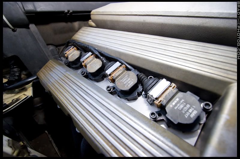
COIL OVER PLUG TESTING

These are some of the basic tests that you can do to check the condition of some of the sensors in an electronically fuel injected motor which in my case was a toyota 4a-fe. And what some faults with the sensors could mean for the operation of the motor.
TPS Image:
http://www4.wave.co.nz/~lakewood/Skyline/ThrottlePositionSensor.jpg
Coolant temp sensor image: http://i37.photobucket.com/albums/e66/das2123/Neon%20Sensor%20Locations/CoolantTempSensorSOHC.jpg
Crankshaft sensor image: http://i288.photobucket.com/albums/ll187/90BlueXJ/Jeep%20assembly/Crankshaft_Position_Sensor_diagram.jpg
MAP sensor image:
http://www.handen.us/caprice/map.gif
Air Temp. sensor image:
http://www.v8sho.com/SHO/images/iatsensor.gif
Fuel Injector Image:
http://www.audizine.com/gallery/data/500/fuel_injector.jpg
Coil Over Plug image:
http://i200.photobucket.com/albums/aa76/shutterflick/IMG_5644.jpg
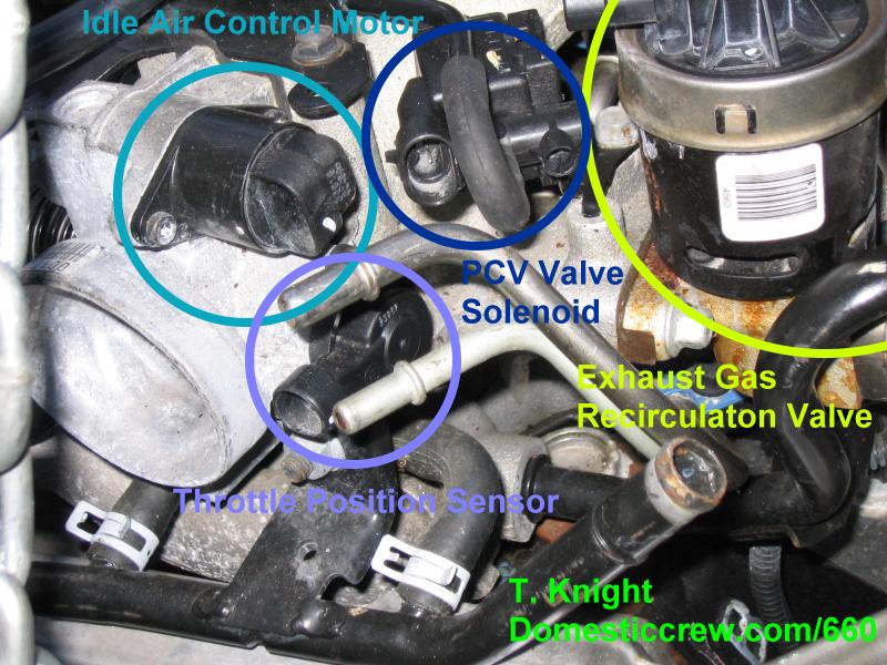
Idle Air Control Sensor and other sensors image:
http://www.domesticcrew.com/images/parts4.jpg
Hi Richard,
ReplyDeleteYou have some really nice work on your blogs here. Shows a high level of understanding.
Good work
Steve